
You have no items in your shopping cart.
Go Kart & Mini Bike Clutches
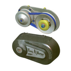
Comet Torque Converter Clutches & Parts
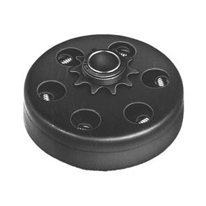
Chain Drive Centrifugal Clutches & Parts

Racing / High Performance Centrifugal Clutches & Parts
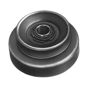
Belt Drive Centrifugal Clutches & Parts
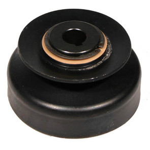
Utility Centrifugal Clutches
Brister Go Kart Clutches & Belts
Go Kart and Mini Bike centrifugal clutches. Belt drive centrifugal clutches. Comet Go Kart and Mini Bike Comet torque converter drive systems. Racing & High Performance Hilliard Clutches.
-
What is a CVT (Continuous Variable Transmission) drive system?
- The basic operating principles of the variable speed drive system of the type used in many RV's are shown in the above illustration. The variable speed drive system normally consists of an engine clutch (1), and a driven unit (3), connected into a system by a "V" type belt (2). The engine clutch is activated by centrifugal force, and the driven unit is torque sensitive, meaning it is responsive to the torque demand of the driven shaft or jackshaft, to adjust the ratio of the system for the power required according to the various conditions. Both the clutch and the driven units are composed of pulleys with moveable sheaves. The moveable sheaves allow for the pitch diameter, offering infinitely variable power ranges.

-
How does it work?
- The drive clutch (1) is activated by centrifugal force from the engine crankshaft. The moveable sheave of the clutch is forced in (as shown above) as the rpm of the engine is increased. This contacts the drive belt (2). The drive belt will then be forced to a larger diameter within the clutch sheaves, thus pulling it to a smaller diameter within the driven unit (3) sheaves. The moveable sheave of the driven unit is (3) forced out, as shown, allowing the belt to seek its smaller, high speed ratio diameter. As this happens, the speed from the engine transferred to the final drive is increased. The illustrations show the variable speed drive system in the extreme low position (broken lines - 2) and the extreme high position (solid lines - 2). The system is infinitely variable between low and high ends.
-
Why use a Comet Torque Converter System?
- Since these devices consist of a "belt" and two "variable pitch pulleys" all working together harmoniously, serving as both clutch AND transmission, we often call them "variable speed drive systems." Weather-proof, completely mechanical and occupying minimum space, they can operate mounted in any position and are adaptable to a wide variety of applications, both stationary and vehicular. Each Comet system is fully automatic and can be used anywhere that control by engine throttle alone is desireable. There are no gears, no complicated controls or levers and neither manual shifting nor clutching is involved in these systems. Utter simplicity makes both cost of this equipment and its installation modest and also reduces future maintenance to a negligible minimum without compromise of performance of versatility. The unique design of the "movable face" in each "driver" and "driven' member cause automatic, infinite variation and thus smooth shifting action between the system's low and high range in immediate response to chainging load and/or travel conditions, with constant optimum ratio between engine and drive wheel thus assured, you get the use of all the power your engine develops. Since ratio selection and "down-shifting" is automatic, braking and vehicle control are enhanced. Even engine and drive train component life (sprocket, chain, bearings, etc) is extended since shifting is smooth and not subject to the hazards of manual control.
-
What are the keys to a proper alignment?
-
Keys to proper operation of the drive system are that the entire system be aligned and adjusted properly. Vital factors in this proper alignment are (1) that the engine crankshaft and drive shaft (jackshaft) be aligned perfectly parallel: (2) that the drive clutch be aligned to have the belt run at its highest speed; (3) that the driven unit sheaves open to the proper dimension for the highest speed range, which is assured by using a belt of the proper width and with the proper collective angles; (4) that the center distance between engine crankshaft and driven shaft be correct for the drive belt as specified; and (5) that the drive belt have the correct outside circumference and proper top width.
Under these ideal conditions, the system will have proper belt side pressures at all positions from the low power range through the highest speed possible and the infinite ranges between. This means positive engagement at all ratio levels and minimum wear on belt, clutch or driven unit. Providing the internal mechanism of the clutch and driven unit are in good shape, the action of the drive system, and the RV should be smooth and accurate in their response at all times. If not parallel, the belt will be pulled to the side of the sheave face, creating uneven and damaging side pressures. This wil not let the belt of the system attain either its proper low end or high speed power range. When not parallel, the system will be erratic in its operation from engagement through the highest speed. Belts will wear very rapidly, and the uneven wear pressures will in many cases cause severe wear and damage to the clutch assembly. The damage caused by this can be likened to that created by a bent crankshaft. The best way to be sure your drive system is properly aligned is to check your drive belt. If there is uneven wear, or fraying edges, it likely means that the system is not properly aligned.
-
-
What are the keys to a proper belt selection
-
There are some common problems that often do not provide or allow for the ideal operation of the drive system and the vehicle. Most of these center on the belt. Care must be taken that the drive belt is the proper length and width, and with the proper collective angle specified for the drive system. If the belt is too short, a number of things can happen that will rob the drive system of its efficiency, including too much friction, wearing out the belt, and not being able to attain the highest speed ratio. A belt too short can easily damage not only the belt itself, but also the drive system.
If the belt is too long, it will also cause loss of efficient operation. With a belt that is too long, the drive system loses its low end power ratios due to belt slippage and its high end ratios because the belt cannot be pulled down into high speed pitch daimeters. The belt that is too long will run out of line at the higher engine rpm's. However, too long is the lesser of the two evils with belt lengths, since it creates less dange to the belt or the drive system.
-
-
What does "Asymmetric" mean?
- A torque converter system concept of driver, driven and belt member, the opposing halves or sides of each member being unequal in angle. The movable face angle of all Comet asymmetric system drivers and drivens is 18 degrees, their "stationary" (opposing) face is 2-1/2 degrees and the Comet asymmetric belt angles likewise correspond. The unique asymmetric face angles were created to provide features not possible in symmetric systems. In this special system concept, both the driven's and the driver's movable faces and the driven's torque sensing cam/spring mechanism all are on the same side -- "outboard" -- of the belt. Thus situated, and even though the movable faces shift back and forth each counter to the direction of the other, it happens that the belt is carried in virtually constant alignment to the stationary faces, since the belt is at all times forced by the movable faces against parallel and nearly vertical stationary faces (just 2-1/2 degrees in angle) which are "inboard" of the belt and mounted directly in line with each other. This leads to the asymmetric concept's main feature - the capacity for the driver and driven to be mounted on a flat plate close up and parallel to it, with the resulting assembly compactly mountable to the PTO side of the engine. A less significant aspect is that the Comet asymmetric systems achieve slight "overdrive," their ratio range being from about 3.2: 1 through around .83:1.
-
What does "Center Distance" mean?
- The exact measurement between the center of the crankshaft to the center of the jackshaft. which is used as a reference to assure correct set-up, when considering a specific belt OC and any particular driver and driven pair's diameters. There always is only one correct CD setting for a given driver, driven and belt.
-
What does "Driven Unit" mean?
- The variable pitch "torque sensitive" pulley mounted on a jackshaft and in-line with the driver. Larger in diameter than the driver and frequently called the torque converter, its greater diameter multiples available torque, that results in a corresponding reduction in RPM of the vehicle's driving wheel(s) in relation to the RPM of the engine. Its combination compression/torsion spring together with the mechanical advantage of its "cams" give it ability to both respond to and also to over-ride the centrifugally-controlled driver member and therby achieve (shift to) a torque multiplication ratio that, at any given moment, is a balance between the engine's power and the torque requirements of changing vehicle load and/or terrain.
-
What does "Driver" mean?
- The drive clutch. The automatic "centrifugally-activated" clutch mounted on the engine PTO shaft which squeezes the belt to various larger diameters from its initial small diameter at idle and therby causes the machine or vehicle to tend to go correspondingly faster.
-
What does "Final Drive" mean?
- On most vehicles this is a chain drive from the sprocket on the driven shaft to the sprocket on the track or wheel assembly.
-
What does "Jackshaft" mean?
- Also referred to as driven shaft. The driven unit and final drive sprocket assembly for driving the track or wheel assembly are located on this shaft. Brake assemblies are also mounted on this shaft on some machines. Must be parallel to the engine's PTO shaft.
-
What does "Moveable Face" mean?
- The face (pulley half) of both driver and driven that shifts position to allow change of "pitch diameter" and thus change of ratio.
-
What does "Outside Circumference" mean?
- The easiest measurement of a drive belt's length. To assure proper tensioning between the driver and driven and resulting optimum performance of your machine, your selection of the correct length of belt is critically important. Too short a belt will damage itself, the engine, driver, driven and/or jackshaft. Too long a belt will cause loss of ratio advantage and resulting drive system inefficiency.
-
What does "Pitch Diameter" mean?
- The diameter of pulley at the point where the center of the belt sides have most friction ability for driving. The minimum pitch diameter is the smallest diameter of pulley's ability; maximum is the largest diameter of pulley's driving ability.
-
What does "Ratio" mean?
-
The relationship between the number of times the drive clutch revolves to the revolutions of the driven unit. Low End Ratio is the ratio between the drive clutch and driven unit when the drive clutch is at its smallest pitch diameter and driven unit is at its largest. The High End Ratio refers to the opposite pitch diameters of the drive clutch and driven unit.
Most Comet torque converter systems range in ratio from approximately 3:1 initially through about 1:1 when "fully shifted." In a broader sense, the over-all ratio of the drive train also includes the sprocket or gear ratio and is determined by multiplying these separate ratios each times the other. Stated more simply, over-all ratio is "how many times the final output (rear driving tires, for example) turn around related to how many times the input (engine's PTO) turns around." Ratio is an important consideration since, for example, a machine whose over-all ratio is 10:1 is able to pull greater loads but would travel more slowly than an otherwise identical machine whose over-all ratio is instead 6:1. Conversely, the latter would travel more quickly though it could not handle as great a load or as difficult a terrain. Of course, other factors which affect the machine speed and load-handling ability are the engine HP and RPM and also the drving tire's diameter.
-
-
What does "Secondary Clutch" mean?
- Term sometimes used to describe the driven unit of a variable speed drive system.
-
What does "Sheaves" mean?
- The pulley faces. Two sheaves form a pulley. The moveable sheave is the pulley face that moves in and out to create different pitch diameters for the drive belt. The stationary sheave is the pulley face that remains in place as the moveable sheave changes postion to create various pitch diameters. Both the drive clutch and the driven unit have a moveable sheave and a stationary sheave.
-
What does "Symmetric" mean?
- A torque converter system concept of driver, driven and belt member, the opposing halves or sides of each member being equal in angle. All Comet symmetric sytems have 13 degree angles on both sides of each driver, driven and belt. In this conventional system concept, the driven's movable face and torque sensing cam/spring mechanism are "inboard" of and thus on the opposite side of belt from the driver's movable face. The driver and driven must be mounted so that when the system is in the neutral/idle mode the centerline of the "V" of each and also of the belt all are in line and parallel with each other. Thus situated, it happens that the belt alignment with the faces is constant since the movable faces both always together simultaneously shift "inboard" and back again. Ratio range of these systems is typically about 3:1 through around 1:1.
-
What does "Torque Sensing" mean?
- Most driven units are torque sensing. They have a spring loaded cam that will respond to the torque load demand of the driven shaft to adjust the ratio of the system for the power required.